Quantcast
Channel: Metering Archives | EEP - Electrical Engineering Portal
Viewing all 49 articles
Browse latest View live

Analog Data Acquisition with Transducers

$
0
0
Current transducer

Current transducer

Transducers measure power system parameters by sampling instrument transformer secondaries. They provide a scaled, low-energy signal that represents a power system quantity that the SA interface controller can easily accept. Transducers also isolate and buffer the SA interface controller from the power system and substation environments. Transducer outputs are dc voltages or currents in the range of a few tens of volts or milliamperes.

Transducers measuring power system electrical quantities are designed to be compatible with instrument transformer outputs.

Potential inputs are based around 120 or 115 Vac, and current inputs accept 0 to 5 A. Many transducers can operate at levels above their normal ranges with little degradation in accuracy provided their output limits are not exceeded. Transducer input circuits share the same instrument transformers as the station metering and protection systems; thus, they must conform to the same wiring standards as any switchboard component. Wiring standards for current and potential circuits vary between utilities, but generally 600-V-class wiring is required, and no. 12 AWG or larger wire is used.

Special termination standards also apply in many utilities. Test switches for “in-service” testing of transducers are often provided to make it possible to test transducers without shutting down the monitored equipment. Transducers may also require an external power source to operate. When this is the case, the reliability of this source is crucial in maintaining data flow.

Transducer outputs are voltage or current sources specified to supply a rated voltage or current into a specific load. For example, full output may correspond to 10 V at up to 1.0 mA or 1.0 mA into 10 kΩ, up to 10 V maximum. Some over-range capability is provided in transducers so long as the maximum current or voltage capability is not exceeded. The over-range can vary from 20 to 100%, depending on the transducer.

However, accuracy is usually not specified for the over-range area. Transducer outputs are usually wired with shielded, twisted-pair cable to minimize stray signal pickup.

In practice, no. 18 AWG conductors or smaller are satisfactory, but individual utility practices differ. It is common to allow transducer output circuits to remain isolated from ground to reduce the susceptibility to transient damage, although some SA controller suppliers provide a common ground for all analogs, often to accommodate electronic multiplexers. Some transducers may also have a ground reference associated with their outputs. Double grounds, where transducer and controller both have ground references, can cause major reliability problems.

Practices also differ somewhat on shield grounding, with some shields grounded at both ends, but it is also common practice to ground shields at the SA controller end only. When these signals must cross a switchyard, however, it is a good practice to not only provide the shielded twisted pairs, but it also to provide a heavy-gauge overall cable shield.

This shield should be grounded where it leaves a station control house to enter a switchyard and where it reenters another control house. These grounds are terminated to the station ground mass, and not to the SA analog grounds bus.

Resource: The Interface between Automation and the Substation by James W. Evans, The St. Claire Group


Measurement of insulation resistance (IR) – Part 1

$
0
0
Megger 10 Kilovolt Insulation Resistance Tester

Megger MIT1020 10-kV insulation resistance testers are all designed specifically to assist the user with the testing and maintenance of high voltage equipment.


Introduction

The measurement of insulation resistance is a common routine test performed on all types of electrical wires and cables. As a production test, this test is often used as a customer acceptance test, with minimum insulation resistance per unit length often specified by the customer. The results obtained from IR Test are not intended to be useful in finding localized defects in the insulation as in a true HIPOT test, but rather give information on the quality of the bulk material used as the insulation.

Even when not required by the end customer, many wire and cable manufacturers use the insulation resistance test to track their insulation manufacturing processes, and spot developing problems before process variables drift outside of allowed limits.


Selection of IR Testers (Megger):

Insulation testers with test voltage of 500, 1000, 2500 and 5000 V are available. The recommended ratings of the insulation testers are given below:

Voltage LevelIR Tester
650V500V DC
1.1KV1KV DC
3.3KV2.5KV DC
66Kv and Above5KV DC

 Test Voltage for Meggering:

When AC Voltage is used, The Rule of Thumb is:
Test Voltage (A.C) = (2X Name Plate Voltage) +1000.

When DC Voltage is used (Most used in All Megger)
Test Voltage (D.C) = (2X Name Plate Voltage).


Equipment / Cable RatingDC Test Voltage
24V To 50V50V To 100V
50V To 100V100V To 250V
100V To 240V250V To 500V
440V To 550V500V To 1000V
2400V1000V To 2500V
4100V1000V To 5000V

Measurement Range of Megger:

Test voltageMeasurement Range
250V DC0MΩ to 250GΩ
500V DC0MΩ to 500GΩ
1KV DC0MΩ to 1TΩ
2.5KV DC0MΩ to 2.5TΩ
5KV DC0MΩ to 5TΩ

Precaution while Meggering

Before Meggering:

Make sure that all connections in the test circuit are tight. Test the megger before use, whether it gives INFINITY value when not connected, and ZERO when the two terminals are connected together and the handle is rotated.

During Meggering:

Make sure when testing for earth, that the far end of the conductor is not touching, otherwise the test will show faulty insulation when such is not actually the case.

Make sure that the earth used when testing for earth and open circuits is a good one otherwise the test will give wrong information. Spare conductors should not be meggered when other working conductors of the same cable are connected to the respective circuits.

After completion of cable Meggering:

  • Ensure that all conductors have been reconnected properly.
  • Test the functions of Points, Tracks & Signals connected through the cable for their correct response.
  • In case of signals, aspect should be verified personally.
  • In case of points, verify positions at site. Check whether any polarity of any feed taken through the cable has got earthed inadvertently.

Safety Requirements for Meggering:

  • All equipment under test MUST be disconnected and isolated.
  • Equipment should be discharged (shunted or shorted out) for at least as long as the test voltage was applied in order to be absolutely safe for the person conducting the test.
  • Never use Megger in an explosive atmosphere.
  • Make sure all switches are blocked out and cable ends marked properly for safety.
  • Cable ends to be isolated shall be disconnected from the supply and protected from contact to supply, or ground, or accidental contact.
  • Erection of safety barriers with warning signs, and an open communication channel between testing personnel.
  • Do not megger when humidity is more than 70 %.
  • Good Insulation: Megger reading increases first then remain constant.
  • Bad Insulation: Megger reading increases first and then decreases.
  • Expected IR value gets on Temp. 20 to 30 decree centigrade.
  • If above temperature reduces by 10 degree centigrade, IR values will increased by two times.
  • If above temperature increased by 70 degree centigrade IR values decreases by 700 times.

How to use Megger

Meggers is equipped with three connection Line Terminal (L), Earth Terminal (E) and Guard Terminal (G).

Megger connections

Megger connections


Resistance is measured between the Line and Earth terminals, where current will travel through coil 1. The “Guard” terminal is provided for special testing situations where one resistance must be isolated from another. Let’s us check one situation where the insulation resistance is to be tested in a two-wire cable.

To measure insulation resistance from a conductor to the outside of the cable, we need to connect the “Line” lead of the megger to one of the conductors and connect the “Earth” lead of the megger to a wire wrapped around the sheath of the cable.


Megger configuration

Megger configuration


In this configuration the Megger should read the resistance between one conductor and the outside sheath.

We want to measure Resistance between Conductor- 2 to sheaths but actually megger measure resistance in parallel with the series combination of conductor-to-conductor resistance (Rc1-c2) and the first conductor to the sheath (Rc1-s).

If we don’t care about this fact, we can proceed with the test as configured. If we desire to measure only the resistance between the second conductor and the sheath (Rc2-s), then we need to use the megger’s “Guard” terminal.

Megger - Connecting guard terminal

Megger - Connecting guard terminal


Connecting the “Guard” terminal to the first conductor places the two conductors at almost equal potential. With little or no voltage between them, the insulation resistance is nearly infinite, and thus there will be no current between the two conductors. Consequently, the Megger’s resistance indication will be based exclusively on the current through the second conductor’s insulation, through the cable sheath, and to the wire wrapped around, not the current leaking through the first conductor’s insulation.

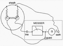
The guard terminal (if fitted) acts as a shunt to remove the connected element from the measurement. In other words, it allows you to be selective in evaluating certain specific components in a large piece of electrical equipment. For example consider a two core cable with a sheath. As the diagram below shows there are three resistances to be considered.

Meggering wiring

Meggering wiring


If we measure between core B and sheath without a connection to the guard terminal some current will pass from B to A and from A to the sheath. Our measurement would be low. By connecting the guard terminal to A the two cable cores will be at very nearly the same potential and thus the shunting effect is eliminated.

To be continued…

An Overview Of Clamp Meter

$
0
0
An AC digital clamp meter

An AC digital clamp meter

Clamp-on ammeter or simply ‘clamp meter’ is an instrument that is used to measure the current flowing through a conductor. An AC Clamp meter basically consists of a current transformer in its jaws, bar CT usually. Utilizing the principle of current transformer, the reading will be displayed.

Whereas a DC clamp meter is quite different. It uses a Hall Effect sensor for measuring the current.


How does an AC clamp meter work?

When the instrument is ‘clamped’ on a conductor, the conductor itself acts as primary and the magnetic flux due to current flowing through the conductor cuts the secondary of CT.

The current in the secondary of the CT is converted to voltage using a current-to-voltage converter. This signal is fed to an analogue to digital converter. A micro controller is usually employed and it will drive the display circuit for the current reading.

Block diagram of an AC clamp meter

Block diagram of an AC clamp meter

How does a DC clamp meter work?

Unlike AC, current transformers cannot be used for measuring direct current. So Hall Effect sensor is used for this purpose. The Hall element used responds to the magnetic flux due to direct current in the conductor which produces voltage across the element.

The developed voltage is proportional to the current in the conductor. So by measuring voltage, current can be determine.

Block diagram of a DC clamp meter

Block diagram of a DC clamp meter

Hall Effect and Hall Effect sensor

Hall effect sensor

Hall effect sensor


The Hall effect is the production of potential difference across an electrical conductor, transverse to current in conductor and a magnetic field perpendicular to the current. This effect was discovered by Edwin Hall in 1879.

A Hall Effect sensor is a transducer that produces a voltage when kept under the influence of magnetic field. The charge carriers experience a force called Lorentz force. Due to this force the charges gets distributed on the surface of material leaving equal and opposite charges on the opposite surface which constitutes a potential difference that exists as long as magnetic field is steady.

In a DC clamp meter Hall Effect sensor is used as a magnetometer. The voltage so developed is proportional to magnetic field and hence to the current.

Even though a clamp meter is mainly used for measuring current, these instruments are added with feature to measure voltage, resistance, frequency etc.

Power Measurement In AC Circuits

$
0
0
GE Watthour Meter

GE Watthour Meter

Power measurement in AC circuits can be quite a bit more complex than with DC circuits for the simple reason that phase shift complicates the matter beyond multiplying voltage by current figures obtained with meters.

What is needed is an instrument able to determine the product (multiplication) of instantaneous voltage and current. Fortunately, the common electrodynamometer movement with its stationary and moving coil does a fine job of this.

Three phase power measurement can be accomplished using two dynamometer movements with a common shaft linking the two moving coils together so that a single pointer registers power on a meter movement scale. This, obviously, makes for a rather expensive and complex movement mechanism, but it is a workable solution.

An ingenious method of deriving an electronic power meter (one that generates an electric signal representing power in the system rather than merely move a pointer) is based on the Hall effect.

The Hall effect is an unusual effect first noticed by E. H. Hall in 1879, whereby a voltage is generated along the width of a current-carrying conductor exposed to a perpendicular magnetic field: (Figure 1).
Figure 1 - Hall effect: Voltage is proportional to current and strength of the perpendicular magnetic field.

Figure 1 - Hall effect: Voltage is proportional to current and strength of the perpendicular magnetic field.


The voltage generated across the width of the flat, rectangular conductor is directly proportional to both the magnitude of the current through it and the strength of the magnetic field. Mathematically, it is a product (multiplication) of these two variables.

Learn more about usage of Hall Effect first discovered by Edwin Hall in 1879.

The amount of “Hall Voltage” produced for any given set of conditions also depends on the type of material used for the flat, rectangular conductor. It has been found that specially prepared “semiconductor” materials produce a greater Hall voltage than do metals, and so modern Hall Effect devices are made of these.

It makes sense then that if we were to build a device using a Hall-effect sensor where the current through the conductor was pushed by AC voltage from an external circuit and the magnetic field was set up by a pair or wire coils energized by the current of the AC power circuit, the Hall voltage would be in direct proportion to the multiple of circuit current and voltage.

Having no mass to move (unlike an electromechanical movement), this device is able to provide instantaneous power measurement: (Figure 2)

Figure 2 - Hall effect power sensor measures instantaneous power.

Figure 2 - Hall effect power sensor measures instantaneous power.


Not only will the output voltage of the Hall effect device be the representation of instantaneous power at any point in time, but it will also be a DC signal! This is because the Hall voltage polarity is dependent upon both the polarity of the magnetic field and the direction of current through the conductor.

If both current direction and magnetic field polarity reverses - as it would ever half-cycle of the AC power – the output voltage polarity will stay the same.

If voltage and current in the power circuit are 90o out of phase (a power factor of zero, meaning no real power delivered to the load), the alternate peaks of Hall device current and magnetic field will never coincide with each other: when one is at its peak, the other will be zero. At those points in time, the Hall output voltage will likewise be zero, being the product (multiplication) of current and magnetic field strength. Between those points in time, the Hall output voltage will fluctuate equally between positive and negative, generating a signal corresponding to the instantaneous absorption and release of power through the reactive load.

The net DC output voltage will be zero, indicating zero true power in the circuit. Any phase shift between voltage and current in the power circuit less than 90o will result in a Hall output voltage that oscillates between positive and negative, but spends more time positive than negative. Consequently there will be a net DC output voltage.

Conditioned through a low-pass filter circuit, this net DC voltage can be separated from the AC mixed with it, the final output signal registered on a sensitive DC meter movement. Often it is useful to have a meter to totalize power usage over a period of time rather than instantaneously. The output of such a meter can be set in units of Joules, or total energy consumed, since power is a measure of work being done per unit time.

Or, more commonly, the output of the meter can be set in units of Watt-Hours.

Mechanical means for measuring Watt-Hours are usually centered around the concept of the motor: build an AC motor that spins at a rate of speed proportional to the instantaneous power in a circuit, then have that motor turn an “odometer” style counting mechanism to keep a running total of energy consumed.

The “motor” used in these meters has a rotor made of a thin aluminum disk, with the rotating magnetic field established by sets of coils energized by line voltage and load current so that the rotational speed of the disk is dependent on both voltage and current.

Resource: Lessons in electric circuits – volume II

Locating underground electrical cable faults

$
0
0
How cable locators work?

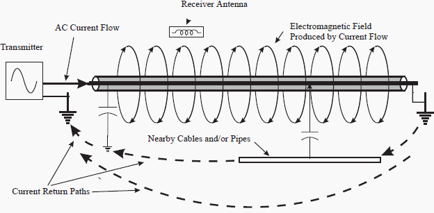
Figure 1 - How cable locators work?

Overview of underground cable faults

Before attempting to locate underground cable faults on direct buried primary cable, it is necessary to know where the cable is located and what route it takes. If the fault is on secondary cable, knowing the exact route is even more critical.

Since it is extremely difficult to find a cable fault without knowing where the cable is, it makes sense to master cable locating and tracing and to do a cable trace before beginning the fault locating process.

Success in locating or tracing the route of electrical cable and metal pipe depends upon knowledge, skill, and perhaps, most of all, experience. Although locating can be a complex job, it will very likely become even more complex as more and more underground plant is installed. It is just as important to understand how the equipment works as it is to be thoroughly familiar with the exact equipment being used.

All popular locators/tracers consist of two basic modules:
  1. The transmitter — an ac generator which supplies the signal current on the underground cable or pipe to be traced.
  2. The receiver — detects the electromagnetic field produced by the transmitted ac current flow. See Figure 1 at the top.

Before starting, it will be helpful to obtain the following information:

  • What type of cable is it?
  • Is the cable the same type all the way along its length?
  • Is the target cable the only cable in the trench?
  • Are there any taps?
  • Is the cable run single phase or multiphase?
  • Is the cable shielded or unshielded?
  • Is the cable direct buried or in conduit?
  • Are there metal pipes or other underground structures under, over or near the target cable?
  • Is the target cable connected to other cables or pipes through grounded neutrals?

This information will help to select the most appropriate locator and to prepare to locate the cable successfully. See Figure 2 below.

Cable under test

Figure 2 - Cable under test


Many transmitters are equipped with some means of indicating the resistance of the circuit that it is trying to pump current through and can indicate a measurement of the current actually being transmitted.

Output current can be checked in several ways as follows:

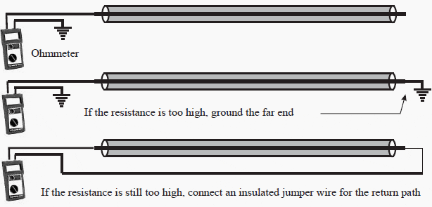
1.By measuring the resistance of the circuit with an ohmmeter

When the resistance is less than approximately 80,000 Ω, there will typically be enough current flowing in the cable to allow a good job of tracing.

This is no guarantee that the transmitted current is passing through the target cable. The measured resistance may be affected by other circuits or pipes electrically connected to the target cable acting as parallel resistances. See Figure 3 below.

Using an ohmmeter to measure resistance of the circuit

Figure 3 - Using an ohmmeter to measure resistance of the circuit


2.By observing the actual signal strength being transmitted by the transmitter

Many transmitters provide a measurement or some indication of output current. A loading indicator on the MEGGER’s Portable Locator Model L1070 blinks to indicate the approximate circuit resistance. A rate of four blinks per second indicates a low resistance, almost a short circuit providing a very traceable signal.

A rate of one blink every three seconds shows a high resistance and a weaker signal.

3.By observing the signal power detected by the receiver

Signal level indicator numbers are displayed digitally on most receivers and older models may display signal power with analog meters. The L1070 has both an analog style signal strength bargraph plus a digital numeric readout. Tracing experience gives the operator the ability to judge whether or not the numbers are high enough.

This is the most practical way to check signal current flow.

Remember, the more current flow through the conductor the stronger the electromagnetic field being detected by the receiver and the further from the conductor being traced the less field is being detected.

Resource: Fault finding solutions by MEGGER 

Analog signals in measurement and control of physical processes

$
0
0
Pressure Transducer provides analog and digital output

Pressure Transducer provides analog and digital output


Instrumentation is a field of study and work centering on measurement and control of physical processes. These physical processes include pressure, temperature, flow rate, and chemical consistency. An instrument is a device that measures and/or acts to control any kind of physical process.

Due to the fact that electrical quantities of voltage and current are easy to measure, manipulate, and transmit over long distances, they are widely used to represent such physical variables and transmit the information to remote locations.

A signal is any kind of physical quantity that conveys information. Audible speech is certainly a kind of signal, as it conveys the thoughts (information) of one person to another through the physical medium of sound. Hand gestures are signals, too, conveying information by means of light.

This text is another kind of signal, interpreted by your English-trained mind as information about electric circuits. In this article, the word signal will be used primarily in reference to an electrical quantity of voltage or current that is used to represent or signify some other physical quantity.

An analog signal is a kind of signal that is continuously variable, as opposed to having a limited number of steps along its range (called digital). A well-known example of analog vs. digital is that of clocks: analog being the type with pointers that slowly rotate around a circular scale, and digital being the type with decimal number displays or a ”second-hand” that jerks rather than smoothly rotates. The analog clock has no physical limit to how finely it can display the time, as its ”hands” move in a smooth, pauseless fashion.

The digital clock, on the other hand, cannot convey any unit of time smaller than what its display will allow for. The type of clock with a ”second-hand” that jerks in 1-second intervals is a digital device with a minimum resolution of one second.

Both analog and digital signals find application in modern electronics. For now, we will limit the scope of this discussion to analog signals, since the systems using them tend to be of simpler design.

With many physical quantities, especially electrical, analog variability is easy to come by. If such a physical quantity is used as a signal medium, it will be able to represent variations of information with almost unlimited resolution.

In the early days of industrial instrumentation, compressed air was used as a signaling medium to convey information from measuring instruments to indicating and controlling devices located remotely. The amount of air pressure corresponded to the magnitude of whatever variable was being measured. Clean, dry air at approximately 20 pounds per square inch (PSI) was supplied from an air compressor through tubing to the measuring instrument and was then regulated by that instrument according to the quantity being measured to produce a corresponding output signal.

For example, a pneumatic (air signal) level ”transmitter” device set up to measure height of water (the ”process variable”) in a storage tank would output a low air pressure when the tank was empty, a medium pressure when the tank was partially full, and a high pressure when the tank was completely full.

Pneumatic (air signal) level ”transmitter” device

Pneumatic (air signal) level ”transmitter” device


The ”water level indicator” (LI) is nothing more than a pressure gauge measuring the air pressure in the pneumatic signal line.

This air pressure, being a signal, is in turn a representation of the water level in the tank. Any variation of level in the tank can be represented by an appropriate variation in the pressure of the pneumatic signal. Aside from certain practical limits imposed by the mechanics of air pressure devices, this pneumatic signal is infinitely variable, able to represent any degree of change in the water’s level, and is therefore analog in the truest sense of the word.

Crude as it may appear, this kind of pneumatic signaling system formed the backbone of many industrial measurement and control systems around the world, and still sees use today due to its simplicity, safety, and reliability. Air pressure signals are easily transmitted through inexpensive tubes, easily measured (with mechanical pressure gauges), and are easily manipulated by mechanical devices using bellows, diaphragms, valves, and other pneumatic devices.

Air pressure signals are not only useful for measuring physical processes, but for controlling them as well. With a large enough piston or diaphragm, a small air pressure signal can be used to generate a large mechanical force, which can be used to move a valve or other controlling device.

Complete automatic control systems have been made using air pressure as the signal medium. They are simple, reliable, and relatively easy to understand. However, the practical limits for air pressure signal accuracy can be too limiting in some cases, especially when the compressed air is not clean and dry, and when the possibility for tubing leaks exist.

With the advent of solid-state electronic amplifiers and other technological advances, electrical quantities of voltage and current became practical for use as analog instrument signaling media. Instead of using pneumatic pressure signals to relay information about the fullness of a water storage tank, electrical signals could relay that same information over thin wires (instead of tubing) and not require the support of such expensive equipment as air compressors to operate:

Pneumatic pressure signals using electrical signals to relay same information over thin wires

Pneumatic pressure signals using electrical signals to relay same information over thin wires


Analog electronic signals are still the primary kinds of signals used in the instrumentation world today (January of 2001), but it is giving way to digital modes of communication in many applications (more on that subject later). Despite changes in technology, it is always good to have a thorough understanding of fundamental principles, so the following information will never really become obsolete.

One important concept applied in many analog instrumentation signal systems is that of ”live zero,” a standard way of scaling a signal so that an indication of 0 percent can be discriminated from the status of a ”dead” system.

Take the pneumatic signal system as an example:

If the signal pressure range for transmitter and indicator was designed to be 0 to 12 PSI, with 0 PSI representing 0 percent of process measurement and 12 PSI representing 100 percent, a received signal of 0 percent could be a legitimate reading of 0 percent measurement or it could mean that the system was malfunctioning (air compressor stopped, tubing broken, transmitter malfunctioning, etc.). With the 0 percent point represented by 0 PSI, there would be no easy way to distinguish one from the other.

If, however, we were to scale the instruments (transmitter and indicator) to use a scale of 3 to 15 PSI, with 3 PSI representing 0 percent and 15 PSI representing 100 percent, any kind of a malfunction resulting in zero air pressure at the indicator would generate a reading of -25 percent (0 PSI), which is clearly a faulty value. The person looking at the indicator would then be able to immediately tell that something was wrong.

Not all signal standards have been set up with live zero baselines, but the more robust signals standards (3-15 PSI, 4-20 mA) have, and for good reason.

Conclusions:

  • A signal is any kind of detectable quantity used to communicate information.
  • An analog signal is a signal that can be continuously, or infinitely, varied to represent any small amount of change.
  • Pneumatic, or air pressure, signals used to be used predominately in industrial instrumentation signal systems. This has been largely superseded by analog electrical signals such as voltage and current.
  • A live zero refers to an analog signal scale using a non-zero quantity to represent 0 percent of real-world measurement, so that any system malfunction resulting in a natural ”rest” state of zero signal pressure, voltage, or current can be immediately recognized.

Resource: Lessons in Electric Circuits Volume I – DC

Overview of Single Phase Induction Type Energy Meter

$
0
0
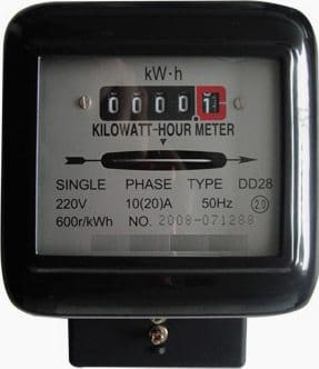
Single-phase induction kilowatt hour meter

Single-phase induction kilowatt hour meter

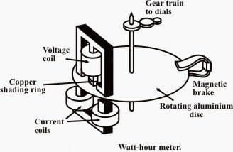
Single phase induction type energy meter is also popularly known as watt-hour meter. This name is given to it. This article is only focused about its constructional features and its working. Induction type energy meter essentially consists of following components:

1. Driving system
2. Moving system
3. Braking system and
4. Registering system

Driving system

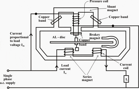
It consists of two electromagnets, called “shunt” magnet and “series” magnet, of laminated construction. A coil having large number of turns of fine wire is wound on the middle limb of the shunt magnet.

This coil is known as “pressure or voltage” coil and is connected across the supply mains. This voltage coil has many turns and is arranged to be as highly inductive as possible. In other words, the voltage coil produces a high ratio of inductance to resistance.

This causes the current and therefore the flux, to lag the supply voltage by nearly 90 degree.
Single-phase induction kilowatt hour meter - Construction

Single-phase induction kilowatt hour meter - Construction


An adjustable copper shading rings are provided on the central limb of the shunt magnet to make the phase angle displacement between magnetic field set up by shunt magnet and supply voltage is approximately 90 degree.

The copper shading bands are also called the power factor compensator or compensating loop. The series electromagnet is energized by a coil, known as “current” coil which is connected in series with the load so that it carry the load current. The flux produced by this magnet is proportional to, and in phase with the load current.

Go to index ↑


Moving system

The moving system essentially consists of a light rotating aluminium disk mounted on a vertical spindle or shaft. The shaft that supports the aluminium disk is connected by a gear arrangement to the clock mechanism on the front of the meter to provide information that consumed energy by the load.

The time varying (sinusoidal) fluxes produced by shunt and series magnet induce eddy currents in the aluminium disc.

The interaction between these two magnetic fields and eddy currents set up a driving torque in the disc.

The number of rotations of the disk is therefore proportional to the energy consumed by the load in a certain time interval and is commonly measured in kilowatt-hours (Kwh).

Go to index ↑


Braking system

Damping of the disk is provided by a small permanent magnet, located diametrically opposite to the a.c magnets. The disk passes between the magnet gaps. The movement of rotating disc through the magnetic field crossing the air gap sets up eddy currents in the disc that reacts with the magnetic field and exerts a braking torque.

By changing the position of the brake magnet or diverting some of the flux there form, the speed of the rotating disc can be controlled.

Go to index ↑


Registering or Counting system

Single-phase induction kilowatt hour meter scheme

Single-phase induction kilowatt hour meter scheme


The registering or counting system essentially consists of gear train, driven either by worm or pinion gear on the disc shaft, which turns pointers that indicate on dials the number of times the disc has turned.

The energy meter thus determines and adds together or integrates all the instantaneous power values so that total energy used over a period is thus known.

Therefore, this type of meter is also called an “integrating” meter.

Working of Single phase induction type Energy Meter

The basic working of  Single phase induction type Energy Meter is only focused on two mechanisms:

  1. Mechanism of rotation of an aluminum disc which is made to rotate at a speed proportional to the power.
  2. Mechanism of counting and displaying the amount of energy transferred.

Lets have a look over these mechanism in few words:


Mechanism of rotation of an aluminum disc

Which is made to rotate at a speed proportional to the power.

The metallic disc is acted upon by two coils. One coil is connected 0r arranged in such a way that it produces a magnetic flux in proportion to the voltage and the other produces a magnetic flux in proportion to the current. The field of the voltage coil is delayed by 90 degrees using a lag coil.

This produces eddy currents in the disc and the effect is such that a force is exerted on the disc in proportion to the product of the instantaneous current and voltage.

A permanent magnet exerts an opposing force proportional to the speed of rotation of the disc – this acts as a brake which causes the disc to stop spinning when power stops being drawn rather than allowing it to spin faster and faster. This causes the disc to rotate at a speed proportional to the power being used.

Go to index ↑


Mechanism of displaying the amount of energy transferred

Based on number of rotation of aluminum disc.

The aluminum disc is supported by a spindle which has a worm gear which drives the register. The register is a series of dials which record the amount of energy used.

The dials may be of the cyclometer type, an odometer-like display that is easy to read where for each dial a single digit is shown through a window in the face of the meter, or of the pointer type where a pointer indicates each digit.

It should be noted that with the dial pointer type, adjacent pointers generally rotate in opposite directions due to the gearing mechanism.

Go to index ↑

HV Instrument Current Transformers in T&D

$
0
0
HV Intrument Current Transformers in T&D

HV Instrument Current Transformers in Transmission and Distribution Systems (on photo: Bus bar-type current transformer used together with transformer bushing, circuit breaker outlet bushing, switchgear bushing, and bus bar, for supplying measuring signal and protitective signal of current. - by Beijing Nobbel Electric Tech Develop Co., Ltd)

Introduction

Electrical measurements on a high-voltage transmission and distribution systems cannot be made practically or safely with direct contact to the power carrying conductors. Instead, the voltages and currents must be brought down to a safe and usable level that can be input into measuring instruments.

This is the whole point task of an instrument transformers CTs and VTs.

They provide replica voltages and currents scaled to more manageable levels. They also bring their replicas to a safe ground potential reference. The most common output range 0 – 5.0 A for currents based on their nominal inputs. Other ranges are used as well.

The majority of these devices are iron core transformers.


Current Transformers

Current transformers (CTs) of all sizes and types find their way into substations to provide the current replicas for metering, controls, and protective relaying. Some will perform well for SA applications and some may be marginal.

CT performance is characterized by:

  1. Turns ratio,
  2. Turns ratio error (ratio correction factor),
  3. Saturation voltage,
  4. Phase angle error, and
  5. Rated secondary circuit load (burden).

CTs are often installed around power equipment bushings, as shown in Figure 1 below:

Bushing current transformer installation

Figure 1 - Bushing current transformer installation


They are the most common types found in medium voltage and high voltage equipment. Bushing CTs are toroidal, having a single primary turn (the power conductor), which passes through their center. The current transformation ratio results from the number of turns wound on the core to make up the primary and secondary.

Lower voltage CTs are often a ‘‘wound’’ construction with both a multiturn primary and secondary winding around their ‘‘E-form’’ or ‘‘shell form’’ core.

Their ratio is the number of secondary turns divided by the number of primary turns. CT secondary windings are often tapped to provide multiple turns ratios. The core cross-sectional area, diameter, and magnetic properties determine the CT’s performance.

As the CT is operated over its nominal current ranges, its deviations from specified turns ratio are characterized by its ratio correction curve sometimes provided by the manufacturer. At low currents, the exciting current of the iron core causes ratio errors that are predominant until sufficient primary magnetic flux overcomes the effects of core magnetizing.

Thus, watt or var measurements made at very low load may be substantially in error both from ratio error and phase shift. Exciting current errors are a function of individual CT construction. They are generally higher for protection CTs than revenue metering CTs by design.

Revenue metering CTs are designed with core cross sections chosen to minimize exciting current effects and their cores are allowed to saturate at fault currents. Protection CTs use larger cores as high current saturation must be avoided for the CT to faithfully reproduce high currents for fault sensing.

The exciting current of the larger core at low primary current is not considered important for protection but can be a problem for measuring low currents. Core size and magnetic properties determine the ability of CTs to develop voltage to drive secondary current through the circuit load impedance (burden).

This is an important consideration when adding SA IEDs or transducers to existing metering CT circuits, as added burden can affect accuracy. The added burden of SA devices is less likely to create metering problems with protection CTs at load levels, but could have undesirable effects on protective relaying at fault levels. In either case, CT burdens are an important consideration in the design.

Experience with both protection and metering CTs wound on modern high silicon steel cores has shown, however, that both perform comparably once the operating current sufficiently exceeds the exciting current if secondary burden is kept low.

Bushing Type Current Transformer with Protection Box

Bushing Type Current Transformer with Protection Box


CT secondary windings are generally uncommitted.

They can be connected in any number of configurations so long as they have a safety ground connection to prevent the windings from drifting toward the primary voltage. It is common practice to connect CTs in parallel so that their current contribution can be summed to produce a new current such as one representing a line current where the line has two circuit breaker connections such as in a ‘‘breaker-and-a-half ’’ configuration.

CTs are an expensive piece of equipment and replacing them to meet new measuring performance requirements is usually cost prohibitive.

However, new technology has developed, which makes it possible for an IED to compensate for CT performance limitations.

This technology allows the IED to ‘‘learn’’ the properties of the CT and correct for ratio and phase angle errors over the CT’s operating range. Thus, a CT designed to feed protection devices can be used to feed revenue measuring IEDs and meet the requirements of IEEE Standard C57.13.

Occasions arise where it is necessary to obtain current from more than one source by summing currents with auxiliary CTs.

There are also occasions where auxiliary CTs are needed to change the overall ratio or shift phase relationships from a source from a wye to a delta or vice versa to suit a particular measuring scheme. These requirements can be met satisfactorily only if the auxiliaries used are adequate. If the core size is too small to drive the added circuit burden, the auxiliaries will introduce excessive ratio and phase angle errors that will degrade measurement accuracy.

Using auxiliary transformer must be approached with caution.

Resource: Automation and the Substation – James W. Evans, The St. Claire Group, LLC


Rogowski Coil Construction

$
0
0
Rogowski Coil Construction

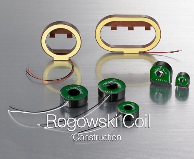
Rogowski Coils For Precision Measurements and Protection


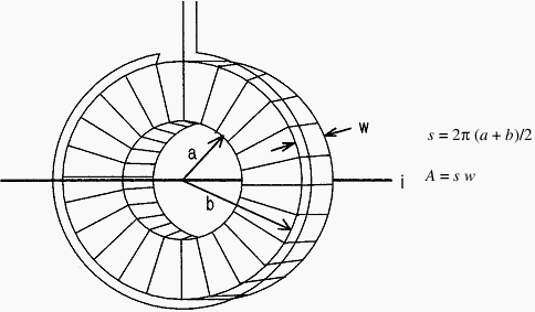
Figure 1 shows the construction of a Rogowski coil, an air-core current transformer that is especially well suited to measuring ripple currents in the presence of a DC component or measuring pulsed currents.
The raw output is proportional to the derivative of the current, and the current can be recovered by an integrator or a low-pass filter.

The output voltage is given by:

Output voltage formula

Rogowski coil construction

Figure 1 - Rogowski coil construction


Where: 

n is the number of turns
A is the cross sectional area of the toroid
s is the centerline circumference

The coil is wound on an air-core form of suitable size for the current conductor. The winding should be applied in evenly spaced turns in one direction only-not back and forth-so that capacitive effects are minimized.

The far end of the winding should be brought back around the circumference of the coil to eliminate the turn formed by the winding itself. The winding must generally be shielded, since the output voltage is relatively low. The shield should be applied so that it does not form a shorted turn through the opening, and the coil should be equipped with an integral shielded output lead with the ground side connected to the coil shield.

Output from the Rogowski coil can either be integrated with a passive network as an R/C low-pass filter or with an operational amplifier.

The advantage of the R/C network is that no power is required for operation. The disadvantages are that it cannot be gated and that the output voltage becomes very low if low-frequency response is required.

Although a toroidal form is shown in the sketch, Rogowski coils are commercially available that are wound in the form of a very long, flexible solenoid that can be wrapped around a conductor and then secured mechanically.

Rogowski coils are largely unaffected by stray fields that have a constant amplitude across the coil. A field gradient across the coil, however, will introduce a spurious output if the field is time varying.

It is good practice to make the coil as small as possible within the electrical and physical constraints of the equipment.

The Rogowski coil can be calibrated from a 50/60-Hz current assuming, of course, that the bandpass of the filter or integrator extends down to those frequencies.

Resource: Electronics Design : A Practitioner’s Guide - eith H. Sueker

Power Measurement In a Three-Phase System

$
0
0
Power Measurement In a Three-Phase System

Power Measurement In a Three-Phase System (on photo: Traditional power meter)

Wattmeter

Electrical power is measured with a wattmeter. A wattmeter consists of a current coil connected in series with load, while the other potential coil is connected parallel with load.

Depending on the strength of each magnetic field movement, the pointer gets affected.

The true or real power is directly shown in a wattmeter. In three-phase systems, power can be measured using several methods. For temporary measurements, a single wattmeter can be used.

However, for permanent measurements, a three-phase wattmeter having two elements is used which indicates both balanced and unbalanced loads.

For an unbalanced load, two wattmeters must be used as shown in the Figure 1.

The total power is calculated by adding the measurement readings given by the two wattmeters. With this method, the power factor can also be obtained.

When using the two-wattmeter method, it is important to note that the reading of one wattmeter should be reversed if the power factor of the system is less than 0.5. In such a case, the leads of one wattmeter may have to be reversed in order to get a positive reading. In the case of a power factor less than 0.5, the readings must be subtracted instead of being added.

The power factor of the three-phase system, using the two-wattmeter method (W1 and W2) can be calculated as follows:

Power factor of the three-phase system

Since the sum and subtraction of readings are done to calculate total true power of a three-phase system, methods shown are not used practically in industry.

Rather three-phase power analyzers are used which are more user-friendly.


Power Factor Meter

What’s common for Beer Mug and Power Factor? Learn. 

It is similar to a wattmeter in principle, only two armature coils are provided with mountings, on a single shaft. They are 90° apart from each other.

Both armature coils rotate as per their magnetic strengths. One coil moves proportional to the restive component of the power, while the other coil moves proportional to the inductive component of the power.

Methods of measuring the power in three-phase systems

Figure 1 - Methods of measuring the power in three-phase systems: (a) One wattmeter method for balanced load; (b) Two wattmeter method for balanced/unbalanced loads

Energy Meter

This shows the amount of power (electric energy) used over a certain period. In a watthour meter, there are two sets of windings.

One is the voltage winding while the other is the current winding. The field developed in the voltage windings causes current to be induced in an aluminum disk. The torque produced is proportional to the voltage and current in the system.

The disk in turn is connected to numeric registers that show electric energy used in terms of kilowatt-hours.

Reference: Practical Troubleshooting of Electrical Equipment and Control Circuits – M. Brown

Electrical Thumb Rules You MUST Follow (Part 8)

$
0
0
Electrical Thumb Rules You MUST Follow (Part 8)

Electrical Thumb Rules You MUST Follow (Part 8)


Continued from part 7: Electrical Thumb Rules You MUST Follow (Part 7)


Three EE thumb rules to follow:

  1. Accuracy Class of Metering CT
  2. Accuracy Class Letter of CT
  3. Accuracy Class of Protection CT

Accuracy Class of Metering CT

Metering Class CT
ClassApplications
0.1 To 0.2Precision measurements
0.5High grade kilowatt hour meters for commercial grade kilowatt hour meters
3General industrial measurements
3 OR 5Approximate measurements

Go back to Index ↑


Accuracy Class Letter of CT

Metering Class CT
Accuracy Class Applications
BMetering Purpose
Protection Class CT
CCT has low leakage flux.
TCT can have significant leakage flux.
HCT accuracy is applicable within the entire range of secondary currents from 5 to 20 times the nominal CT rating. (Typically wound CTs.)
LCT accuracy applies at the maximum rated secondary burden at 20 time rated only. The ratio accuracy can be up to four times greater than the listed value, depending on connected burden and fault current. (Typically window, busing, or bar-type CTs.)

Go back to Index ↑


Accuracy Class of Protection CT

ClassApplications
10P5Instantaneous over current relays & trip coils: 2.5VA
10P10Thermal inverse time relays: 7.5VA
10P10Low consumption Relay: 2.5VA
10P10/5Inverse definite min. time relays (IDMT) overcurrent
10P10IDMT Earth fault relays with approximate time grading:15VA
5P10IDMT Earth fault relays with phase fault stability or accurate time grading: 15VA

Go back to Index ↑

Instrument transformers (CTs, VTs) in the system

$
0
0
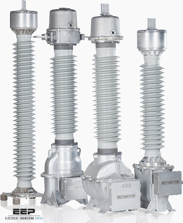
Instrument transformers from ABB

Instrument transformers from ABB

Three main tasks of CTs and VTs

The three main tasks of instrument transformers are:

  1. To transform currents or voltages from a usually high value to a value easy to handle for relays and instruments.
  2. To insulate the metering circuit from the primary high voltage system.
  3. To provide possibilities of standardizing the instruments and relays to a few rated currents and voltages.

Instrument transformers are special types of transformers intended to measure cur- rents and voltages. The common laws for transformers are valid.

Here we will cover six important aspects of using instrument transformer in the power system:

  1. Terminal designations for current transformers
  2. Secondary grounding of current transformers
  3. Secondary grounding of voltage transformers
  4. Connection to obtain the residual voltage
  5. Fusing of voltage transformer secondary circuits
  6. Location of current and voltage transformers in substations

1. Terminal designations for current transformers

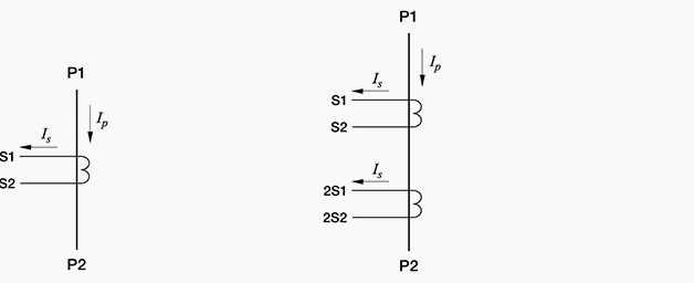
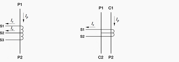
According to IEC publication 60044-1, the terminals should be designated as shown in the following diagrams. All terminals that are marked P1, S1 and C1 are to have the same polarity.

Figure 1 left - Transformer with one secondary winding; Figure 2 right - Transformer with two secondary windings

Figure 1 left – Transformer with one secondary winding; Figure 2 right – Transformer with two secondary windings


Figure 3 left - Transformer with one secondary winding which has an extra tapping; Figure 4 right - Transformer with two primary windings and one secondary winding

Figure 3 left – Transformer with one secondary winding which has an extra tapping; Figure 4 right – Transformer with two primary windings and one secondary winding


Go back to main aspects ↑

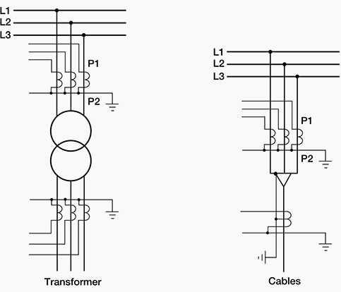
2. Secondary grounding of current transformers

To prevent the secondary circuits from attaining dangerously high potential to ground, these circuits have to be grounded. Connect either the S1 terminal or the S2 terminal to ground.

For protective relays, ground the terminal that is nearest to the protected objects. For meters and instruments, ground the terminal that is nearest to the consumer.

When metering instruments and protective relays are on the same winding, the protective relay determines the point to be grounded.
  • If there are unused taps on the secondary winding, they must be left open.
  • If there is a galvanic connection between more than one current transformer, these shall be grounded at one point only (e.g. differential protection).
  • If the cores are not used in a current transformer they must be short-circuited be- tween the highest ratio taps and shall be grounded.

It is dangerous to open the secondary circuit when the CT is in operation. High voltage will be induced.
Figure 5 left - Transformer; Figure 6 right - Cables

Figure 5 left – Transformer; Figure 6 right – Cables


Figure 7 - Busbars

Figure 7 – Busbars


Go back to main aspects ↑

3. Secondary grounding of voltage transformers

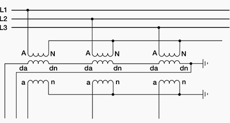
To prevent secondary circuits from reaching dangerous potential, the circuits shall be grounded. Grounding shall be made at only one point on a voltage transformer secondary circuit or galvanically interconnected circuits.

A voltage transformer, which on the primary is connected phase to ground, shall have the secondary grounding at terminal n.

A voltage transformer, with the primary winding connected between two phases, shall have the secondary circuit, which has a voltage lagging the other terminal by 120 degrees, grounded. Windings not in use shall be grounded.

Figure 8 - Voltage transformers connected between phases

Figure 8 – Voltage transformers connected between phases


Figure 9 - set of voltage transformers

Figure 9 – set of voltage transformers


Go back to main aspects ↑

4. Connection to obtain the residual voltage

The residual voltage (neutral displacement voltage, polarizing voltage) for earth-fault relays can be obtained from a voltage transformer between neutral and ground, for instance at a power transformer neutral.

It can also be obtained from a three-phase set of voltage transformers, which have their primary winding connected phase to ground and one of the secondary windings connected in a broken delta.

Figure 10 illustrates the measuring principle for the broken delta connection during an earth-fault in a high-impedance grounded (or ungrounded) and an effectively grounded power system respectively.

From the figure, it can be seen that a solid close-up earth-fault produces an output voltage of

Ursd = 3 x U2n

in a high-impedance earthed system and

Ursd = U2n

in an effectively grounded system. Therefore a voltage transformer secondary voltage of

U2n = 110 / 3 V

is often used in high-impedance grounded systems and U2n = 110 V in effectively grounded systems. A residual voltage of 110 V is obtained in both cases. Voltage transformers with two secondary windings, one for connection in Y and the other in broken delta can then have the ratio:

Voltage transformers ratio formulas

for high-impedance and effectively grounded systems respectively. Nominal voltages other than 110 V, e.g. 100 V or 115 V, are also used depending on national standards and practice.

Figure 10 - Residual voltage (neutral displacement voltage) from a broken delta circuit

Figure 10 – Residual voltage (neutral displacement voltage) from a broken delta circuit

5. Fusing of voltage transformer secondary circuits

Fuses should be provided at the first box where the three phases are brought together. The circuit from the terminal box to the first box is constructed to minimize the risk of faults in the circuit.

It is preferable not to use fuses in the voltage transformer terminal box, as this will make the supervision of the voltage transformers more difficult. The fuses in the three-phase box enable a differentiated fusing of the circuits to different loads like protection and metering circuits.

The fuses must be selected to give a fast and reliable fault clearance, even for a fault at the end of the cabling. Earth faults and two-phase faults should be checked.

Go back to main aspects ↑

6. Location of current and voltage transformers in substations

Instrument transformers are used to supply measured quantities of current and voltage in an appropriate form to controlling and protective apparatus, such as energy meters, indicating instruments, protective relays, fault locators, fault recorders and synchronizers.

Instrument transformers are thus installed when it is necessary to obtain measuring quantities for the above mentioned purposes.

Typical points of installation are switchbays for lines, feeders, transformers, bus couplers, etc., at transformer neutral connections and at the busbars.

Figure 11 - Current and voltage transformers in a substation

Figure 11 – Current and voltage transformers in a substation


Go back to main aspects ↑

Location in different substation arrangements

Below are some examples of suitable locations for current and voltage transformers in a few different switchgear arrangements.

Figure 12 - Double busbar station

Figure 12 – Double busbar station


Figure 13 - Station with transfer busbar

Figure 13 – Station with transfer busbar


Figure 14 - Double breaker and double busbar station

Figure 14 – Double breaker and double busbar station


Figure 15 - Sectionalized single busbar station

Figure 15 – Sectionalized single busbar station


Go back to main aspects ↑

Reference: Instrument Transformers Application Guide – ABB

7 Practical Tips For Installing a Good Measuring System

$
0
0
7 Practical Tips For Installing a Good Measuring System

7 Practical Tips For Installing a Good Measuring System (on photo: ABB’s low voltage switchgear type MNS; by controlequipment.ie)

1. Start from the need: what do I want to measure?

A single electric parameter or all the electric parameters

There are different product families on the market: instruments that measure a single electric parameter (voltage, current, frequency, phase angle cosϕ), generally used in single phase systems, as instrumentation on the machine, and instruments that enable all the electric parameters to be measured and displayed, both for the single phase and in the three-phase system.

This type of multifunction instrument is ideal in panels in which space is limited, in panels of substations and in main industrial panels.

If not only electric parameters need to be monitored but also energy consumption needs to be checked, measuring instruments that also include an active and reactive energy count have to be selected.


2. Selecting the measuring system

Single parameter, multifunction, analogue or digital instrument

Multi-Functional Power Meter

Multi-Functional Power Meter (photo credit: powermeterstore.com)


The instrument should be selected according to the type of distribution system. In a single-phase system, analogue and digital instruments are selected for measuring voltage, current, frequency and the power factor.

In a three-phase system instruments can be installed that measure the single electric parameter, one per phase, or a voltmeter and an current can be installed together with the voltage and current switches, which enable the measurements to be displayed in sequence, phase by phase.

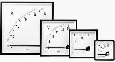
Choosing an analogue instrument ensure good reading stability, due to the mechanical inertia of the needle and the fact that the reader immediately knows whether the instrument is working normally or whether the reading is off-scale.

The analogue instrument indicates the point on the measuring scale in which it finds itself, showing the upper and lower limits.

Moving-coil meters

Moving-coil meters (photo credit: directindustry.com)


In digital instruments this indication is not possible as the only reference is the reading of the value on the display, for example, of the current. Some measuring instruments have bar indicators that show the current level as a percentage of the set full scale.

Choosing a digital instrument guarantees better readability, also in poor lighting, specially for instruments with LED displays, and an immediate reaction to the measurement variation.


3. Sizing the system, choosing the CT

Sizing the measuring system starts with knowing the main parameters of the plant; in particular, starting from the characteristics of the protection switch, the type of distribution system, rated current, rated voltage and bar type can be known.

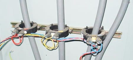
Current transformers used in metering equipment for 3-phase 400A electricity supply

Current transformers used in metering equipment for 3-phase 400A electricity supply (photo credit: Wikipedia)


After the type of instrument has been defined that is most suitable for requirements, if the measurement is conducted through indirect insertion, the accessories of the measuring system such as current and voltage transformers must be chosen carefully.

If an 800 A current has to be measured, in most cases the instrument cannot be connected directly to the line. A current transformer that is suitable for the application must therefore be selected. The chosen parameters of a current transformer are not only rated current, secondary current and power but also the type of assembly. Flexible and stiff cables or bars for carrying power can be installed in a power panel.

The transformers can be of different types, depending on the assembly system: a through cable or a cable with a wound primary, transformers for assembly on horizontal or vertical bars.


4. Cabling and wiring diagrams

Connecting analogue instruments is very simple; it in fact suffices to connect the phase and neutral cables to the instrument’s.terminal. Two cables fo the auxiliary supply must always be connected for digital instruments.

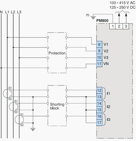
Power meter series 800 - wire connection with 3 CTs and no PT

Power meter series 800 – wire connection with 3 CTs and no PT


Multifunction instruments can be used in different distribution systems.

In three-phase systems with distributed neutral three current transformers are required. In three-phase systems without distibuted neutral in which the loads are balanced and symmetrical, an aron insertion can be carried out, i.e. two current transformers rather than three can be used; the instrument will calculate by difference the third phase that is not measured directly, considering it to be the same as the other two.

In multifunction instruments not only the cables connected to the measurement, but also the RS485 serial port and the analogue and digital outputs and inputs have to be cabled.


5. Protecting the instrument and earthing

In order to ensure that the instrument is properly protected, fuses must always be fitted to the supply cables of digital instruments and to the voltmeter measuring inputs.

Earthing the secondaries of the CTs ensures an earth connection if the transformer develops a fault and does not affect the measurement. If there is a great potential difference between neutral and earth, this could affect the measurement negatively, in the case of instruments with measuring inputs that are not galvanically insulated.


6. Setting digital instruments

Before digital instruments start operating they must be set with the parameters of the measuring system and the communication parameters. The main measuring parameters are the transformation ratios of the CTs and of the VTs, which are defined as the mathematical ratio between the nominal value and the value of the secondary;

For example, setting the transformation ratio of an CT CT3/100 with a secondary at 5 A means setting kCT = 100: 5 = 20


7. Troubleshooting during final testing

The main problems that arise during the test phase may be due to incorrect installation of the instruments and the accessories. Always check that the wiring complies with the instruction manual.

Errors during installation

The following errors are those that are most frequently committed when installing a measuring instrument:

  • Inverting the secondaries of the CTs
  • Inverting the phases of the current and voltage measuring inputs
  • Failure to eliminate the short circuit of the secondaries of the CTs
  • Setting an incorrect transformer ratio.

Reference: Practical guide to electrical measurements in low voltage switchboards – ABB (Download)

The Consumer Power Substation With Metering On Medium Voltage Side

$
0
0
The Consumer Power Substation With Metering On Medium Voltage Side

The Consumer Power Substation With Metering On Medium Voltage Side (photo credit: alanya.tv)

Nominal voltage 1kV – 35kV

A consumer power substation with metering on medium voltage side is an electrical installation connected to a utility supply system at a nominal voltage usually between 1kV – 35kV, which for example may supply a single MV/LV transformer (exceeding generally 1250 kVA), several MV/LV transformers or one or several MV/LV secondary substations.

The single line diagram and the layout of a substation with MV metering depend on the complexity of the installation and the presence of secondary substations.

For example a substation may:
  • Include one single room containing the MV switchboard, the metering panel, the transformer(s) and the low voltage main distribution board(s),
  • Supply one or several transformers, each installed in a dedicated room including the corresponding main LV distribution switchboard
  • Supply one or several secondary MV/LV substations.

Functions of the substation with MV metering

  1. Connection to the MV network
  2. MV/LV Transformers and internal MV distribution
  3. Metering
  4. Local emergency generators
  5. Capacitors
  6. LV main switchboard
  7. Simplified electrical network diagram

1. Connection to the MV network

Connection to the MV network can be made:

  1. By a single service cable or overhead line,
  2. By dual parallel feeders via two mechanically interlocked load-break switches
  3. Via a ring main unit including two load-break switches.
SM6 medium voltage switchgear, Schneider Electric

SM6 medium voltage switchgear, Schneider Electric (photo credit: ezois.ru)


Go back to Index ↑


2. MV/LV Transformers and internal MV distribution

As well as for substation with LV metering, only oil-immersed and dry type cast-resin transformers are allowed with the same rules of installation. When the installation includes several MV/LV transformers and/or secondary MV/ LV substations an internal MV distribution network is required.

Trihal - Dry-type transformer 1600 kVA 10/0,42kV connected to busbar system Canalis KTA 2500A (Schneider Electric)

Trihal – Dry-type transformer 1600 kVA 10/0,42kV connected to busbar system Canalis KTA 2500A (Schneider Electric)


According to the required level of availability, the MV supplies to the transformers and the secondary substations may be made:

  1. By simple radial feeders connected directly to the transformers or to the secondary substations
  2. By one or several rings including the secondary MV/LV substations
  3. By duplicate feeders supplying the secondary MV/LV substations.

For the two latter solutions the MV switchboard located in each secondary substation includes two load break switch functional units for the connection of the substation to the internal MV distribution and one transformer protection unit, for each transformer installed in the substation. The level of availability can be increased by using two transformers operating in parallel or arranged in dual configuration with an automatic change over system.

It is not recommended to use MV/LV transformers above 2500 kVA due to: The high level of the short circuit current generated on the main LV switchboard and the number of LV cable required for the connection of the transformer to the LV switchboard.

Go back to Index ↑


3. Metering

The characteristics and the location of the VT’s and CT’s dedicated to the metering shall comply with the utility requirements.

Medium voltage SM6 metering cubicle GBC

Medium voltage SM6 metering cubicle GBC (photo credit: schneider-electric.be)


The VT’s and CT’s are generally installed in the MV switchboard. A dedicated functional unit is in most of the cases required for the voltage transformers while the current transformers may be contained in the functional unit housing the circuit breaker ensuring the general protection of the substation.

The panel that contains the meters shall be accessible by the utility at any time.

Go back to Index ↑


4. Local emergency generators

Emergency standby generators are intended to maintain the power supply to the essential loads in the event of failure of the utility power supply. According to the energy needs an installation may contains one or several emergency generators.

The generators can be connected:

At MV level to the MV main substation (see Fig. B34).The generator(s) may be sized either for the supply of the whole installation or for a part only. In this case a load shedding system must be associated to the generator(s).

Connection of emergency generators at MV level

Figure B34 – Connection of emergency generators at MV level


At LV level on one or several LV switchboards requiring an emergency supply. At each location, the loads requiring an emergency supply may be grouped on a dedicated LV busbar supplied by a local generator (see Fig. B32).

Emergency generator at LV Level

Figure B32 – Emergency generator at LV LevelEmergency generator at LV Level


Go back to Index ↑


5. Capacitors

Capacitors are intended to maintain the power factor of the installation at the contractual value specified by the utility. The capacitor banks can be fixed or adjustable by means of steps.

They can be connected:

  • At MV level to the main MV substation
  • At LV level on LV switchboards.
Capacitor banks panel

Capacitor banks panel (photo credit: schneider-electric.be)


Go back to Index ↑


6. LV main switchboard

Every MV/LV transformer is connected to a main LV switchboard complying with the requirements listed for substation with LV metering.

Main low voltage switchgear, type PRISMA P, Schneider Electric

Main low voltage switchgear, type PRISMA P, Schneider Electric (photo credit: skaaret.as)


Go back to Index ↑


7. Simplified electrical network diagram

Consumer substation with MV metering

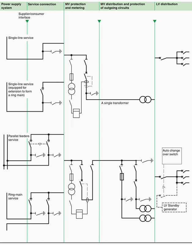
Figure B35 – Consumer substation with MV metering


The diagram (Fig. B35) shows:

  • The methods of connection of a MV/LV substation to the utility supply:
    • Spur network or single-line service
    • Single line service with provision for future connection to a ring or to dual parallel feeders
    • Dual parallel feeders
    • Loop or ring-main service
  • General protection at MV level
  • MV metering functions
  • Protection of MV circuits
  • LV distribution switchboard
Compared with a substation with LV metering, a substation with MV metering includes in addition:
  • A MV Circuit breaker functional unit for the general protection of the substation
  • A MV metering functional unit
  • MV Functional units dedicated to the connection and the protection of:
    • MV/LV transformers
    • MV feeders supplying secondary substations
    • MV capacitor banks
    • Emergency generators

The general protection usually includes protection against phase to phase and phase to earth faults. The settings must be coordinated with the protections installed on the feeder of the primary substation supplying the installation.

Go back to Index ↑

Reference: Electrical Installation Guide 2015 – Schneider Electric (Download)

Understanding The Ratios Of Magnetic HV Instrument Current Transformers

$
0
0
ratio-magnetic-hv-instrument-current-transformers-fp
Understanding The Ratios Of Magnetic HV Instrument Current Transformers
Understanding The Ratios Of Magnetic HV Instrument Current Transformers (photo credit: ABB)

Primary & secondary windings

The primary winding is a part of the network, carrying the actual load current. The transformer’s secondary circuits usually consist of several units, each of them having its own magnetic core and winding. The transformer has a rated current transforming ratio, like for example 200/1 A, stating the rated primary current and the corresponding rated secondary current.

It is often desired that the transformer should have multiple ratios. This can mean that all or some of the windings have more than one ratio from which to choose. The selection of the desired ratio can be done on site and changed later if so needed.

For doing current transformers with multiple ratios there are two possibilities, namely:

  1. Primary re-connectable or
  2. Secondary re-connectable.
Secondary re-connectable (left) and primary re-connectable (right) current transformer winding presentation
Figure 1 – Secondary re-connectable (left) and primary re-connectable (right) current transformer winding presentation

Primary re-connectable means that the primary circuit connection has to be changed to change the ratio. Usually only two connection alternatives exist having a ratio of 2:1.

An example below:

200–400/1/1 A

The ratio can be selected to be either 200/1 A or 400/1 A. The selection affects all the secondary windings. The secondary core data, except for the ratio, remains the same with either of the ratio selections. The underlined value shows the presently utilized ratio.

Secondary re-connectable means that the ratio can be changed by utilizing tappings in each of the secondary cores. More than two ratio alternatives can exist, with uneven ratios.

An example below:

600/1 + 200-300-400/1/1 A

One of the cores (600/1 A) is having a fixed ratio, whereas with the two other cores the ratio can be selected by means of a secondary re-connection. The secondary core data will change along with the ratio selection. The underlined value shows the presently utilized ratio, where the selection possibility exists.

A 66 kV outdoor-mounted oil-insulated one-phase current transformer with three secondary cores
Figure 2 – A 66 kV outdoor-mounted oil-insulated one-phase current transformer with three secondary cores

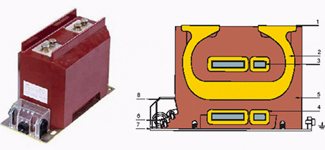
A 12 kV indoor epoxy resin-cased one-phase support current transformer with two secondary cores
Figure 3 – A 12 kV indoor epoxy resin-cased one-phase support current transformer with two secondary cores

Where:

  1. Medium voltage terminals
  2. Primary winding
  3. Magnetic circuit
  4. Secondary winding
  5. Epoxy body
  6. Secondary outlets
  7. Base plate
  8. Cover of secondary terminals used for outlet sealing

With an ideal current transformer under short-circuited conditions, there is always a balance with the ampere turns, meaning that the product of primary current and primary winding turns equals the product of secondary current and secondary winding turns.

I× N1 = I× N2

Principle presentation of a magnetic current transformer
Figure 4 – Principle presentation of a magnetic current transformer

Equivalent circuit

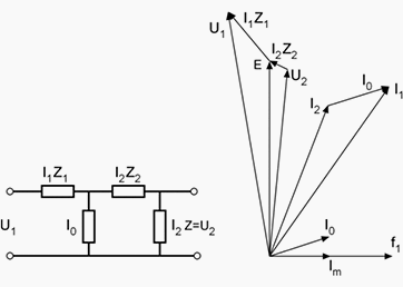
The behavior of current transformers and the conformities to basic electrical laws can be demonstrated by the use of equivalent circuit shown below.

Equivalent circuit of a magnetic current transformer
Figure 5 – Equivalent circuit of a magnetic current transformer

From the above equivalent circuit, it can be seen that with a non-ideal transformer there are always some errors included in the measurement. These errors are mainly caused by the excitation current (Ie) and the load current (I2), which introduces both ratio errors and angle errors between the reduced primary current and the actual secondary current.

It can also be further observed that if the CT secondary side is left open-circuited (infinite burden connected), the whole primary current starts to excite the CT, resulting in overloading and induced dangerous voltage in the secondary terminals.

The detailed core data describes the core performance with respect to the intended application. This data can be expressed according to guidelines of one of the several international standards, like IEC, British Standards or IEEE. The following is based on the standards provided by IEC [3.14].

The issue is approached through an example. It is assumed here that a three-phase current transformer set, having the below shown data labels, is used for energy measurement and overcurrent protection.

200-400/1/1 A

 1S1-1S2 5VA class 0.5 Fs5
 1S1-1S3 10VA class 0.5 Fs5
 2S1-2S2 10VA 5P10
 2S1-2S3 20VA 5P10
 12/28/75kV 50Hz 40(1s)/100kA

200-400/1/1A

The transformer has dual-ratio re-connection (from secondary) possibilities and two second-ary cores. The rated primary current is either 200A or 400A. The rated secondary current is 1A.

If not otherwise stated, the maximum continuous allowed primary current is the same as the rated primary current. In some cases, it is specially stated that the maximum allowed continuous current is for example 120% of the rated primary current.
  • 1S1-1S2 5VA class 0.5 Fs5
  • 1S1-1S3 10VA class 0.5 Fs5

The first secondary core is for measuring. The ratio selection between 200/1A and 400/1A is made by the secondary re-connection. Connection between 1S1 and 1S2 gives a ratio of 200/1A whereas 1S1 and 1S3 gives a ratio of 400/1A.

The accuracy class of this measuring core is 0.5. To comply with this accuracy class, the transformer has to fulfill certain requirements regarding current error and phase displacement error as shown below. These limits apply to secondary burdens between 25-100% of the rated burden.

Current transformer measurement requirements for classes 0.5 and 0.2 according to IEC standards
Figure 6 – Current transformer measurement requirements for classes 0.5 and 0.2 according to IEC standards. Plotted lines show the behavior of the transformer used in above example

The secondary rated burden of the measurement core is changing according to the used secondary re-connection (tapping). With the highest ratio (400/1A) the rated burden is 10VA and with the lowest ratio (200/1A) the rated burden is 5VA.

The instrument security factor (Fs) describes the transformer’s saturation with rated primary current multiples. This is an important factor for securing the capability of the connected measuring devices to withstand the injected currents during power system faults.

Primary current of magnitude five times (Fs 5) the rated primary current causes a combined error of at least 10%. The protective feature for measurement devices is the better the lower the overcurrent limit factor is. It should be further noticed that the given overcurrent limit factor value applies with the stated rated burden and is subject to change if the actual burden differs from the rated burden.

  • 2S1-2S2 10 VA 5P10
  • 2S1-2S3 20 VA 5P10

The second secondary core is for protection. The ratio selection between 200/1A and 400/1A is made by the secondary re-connection. Connection between 1S1 and 1S2 gives a ratio of 200/1A whereas 1S1 and 1S3 gives a ratio of 400/1A.

The secondary rated burden of the measurement core changes according to the used secondary re-connection (tapping). With the highest ratio (400/1A) the rated burden is 20VA and with the lowest ratio (200/1A) the rated burden is 10VA.

The marking 5P10 is a combination of two things, namely the accuracy class of 5P and accuracy limit factor of 10. The complete marking 5P10 indicates that the composite error will not exceed 5% with ten times the rated primary current when the rated secondary burden is connected.

The accuracy limit factor changes in relation to the actual connected burden. For example, if the ratio of 400/1A was used and the total connected actual burden, including all leads and connected devices, was 15VA, the accuracy limit factor would then result as follows:

20/15 × 10 ≈ 13.3 (Actual accuracy limit factor)

If the ratio of 200/1A was used instead, the actual accuracy limit factor would be:

10/15 × 10 ≈ 6.7 (Actual accuracy limit factor)


12/28/75kV

12kV is the highest voltage for the equipment (RMS value). 28kV is the rated power frequency withstanding voltage (RMS test value). 75kV is the rated lightning impulse withstanding voltage (peak test value).

40(1s)/100kA

This states the short thermal current withstanding level being 40kA/1s (RMS) and the dynamic current withstanding level being 100kA (peak value).

Get Free Instrument Transformers Application Guide:  Download

Reference // Distribution Automation Handbook (prototype)  – ABB

The post Understanding The Ratios Of Magnetic HV Instrument Current Transformers appeared first on EEP - Electrical Engineering Portal.


Current and voltage sensors as an alternative to traditional CTs and VTs

$
0
0
Current and voltage sensors as an alternative to traditional CTs and VTs
Current and voltage sensors as an alternative to traditional CTs and VTs (on photo: The current snsors type KECA 80 Cxxx are intended for use in current measurement in medium voltage air insulated switchgear type UniGear ZS1 12/17.5kV)

Sensors as alternative

As an alternative for traditional primary current and voltage measurement techniques, the use of sensor technique is gaining field. This technique is typically applied to current and voltage measurement in medium-voltage metal-enclosed indoor switchgears.

There are many undeniable advantages with sensors when compared to the traditional solutions:

  • Non-saturable
  • High degree of accuracy
  • Personnel safety
  • Extensive dynamic range
  • Small physical size and weight
  • Possibility to combine current and voltage measurement into one physical device with compact dimensions
  • Environmental friendliness (less raw material needed)

The above statements are discussed in more detail in the following paragraphs while introducing the sensor techniques and the actual related apparatus. Let’s say a word about each type of sensor and some conclusion at the end:

  1. Current sensors
  2. Voltage sensors
  3. Combined sensors
  4. Conclusion and answer on why sensors are not 100% alternative

Current Sensors

The measurement of current is based on the Rogowski coil principle. The Rogowski coil is a toroidal coil without an iron core. The coil is placed around the current-carrying primary conductor. The output from the coil is a voltage signal, proportional to the derivative of the primary current.

The signal is then integrated in the secondary device to produce a signal proportional to the primary current wave form.

Since no iron core is employed, no saturating occurs, unlike with traditional current transformers.

The open-circuited traditional current transformer produces dangerous voltages to the secondary side and lead to a serious overloading of the transformer. Since the output from the current sensor is a voltage signal, the open-circuited secondary conditions do not lead to a dangerous situation, neither to human beings nor apparatus.

Principle of current measurement based on Rogowski coil
Figure 1 – Principle of current measurement based on Rogowski coil

The transmitted signal is a voltage:

Uout = M · dip / dt

For a sinusoidal current under steady state conditions the voltage is:

Uout = M · j · ω · Ip

With traditional current transformers, the ratio of the CT is fixed to one value, or in case of multi-ratio CTs, to several values. These values are chosen according to the specific application needs and load currents.

As a result, one, for example medium-voltage primary switchgear, installation usually requires several CT types.

With a current sensor, the situation is simpler, since one type of sensor covers a range of primary currents and in optimum case the whole installation can be covered with one type only.

To give an idea of the secondary-voltage signal level, one fixed point (ratio) inside the rated current range could be 400 A primary value, typically corresponding to 150 mV secondary signal level.

Example on current sensor’s rated current range
Figure 2 – Example on current sensor’s rated current range

The problems related to saturating iron core in conventional current transformers can be overcome with the sensor technology. The below figure demonstrates the difference between the secondary-signal performance for both traditional current transformer and current sensor.

Principle comparison of current sensor and current transformer secondary-signal performance as a function of combined error (ε) and primary current (IP)
Figure 3 – Principle comparison of current sensor and current transformer secondary-signal performance as a function of combined error (ε) and primary current (IP)

Due to the compact size of a current sensor (no iron core), there are better possibilities to integrate the measurement devices inside other constructional parts of a metal-enclosed switchgear.

An example of this possibility would be the integration of a sensor inside plug-in-type medium-voltage cable terminations.
On the left a current sensor inside cable plug-in termination and on the right a current sensor inside conventional housing
Figure 4 – On the left a current sensor inside cable plug-in termination and on the right a current sensor inside conventional housing

Go back to Types ↑


Voltage Sensors

The measurement of voltage is based on voltage divider. Two main types are available, namely the capacitive one and the resistive one. The output in both cases is a low-level voltage signal. The output is linear throughout the whole rated measurement range.

The considerations and protection methods against the ferroresonance phenomena, discussed with traditional voltage transformers, are not applicable with voltage sensors.

Two main principles for voltage sensor implementation
Figure 5 – Two main principles for voltage sensor implementation

As with current sensors, also with voltage sensors it is possible to cover certain voltage range with one sensor type. To give an idea of the secondary voltage signal level, one fixed point (ratio) inside the rated voltage range could be 20000/√3V primary value, typically corresponding to 2/√3V secondary-signal level.

Voltage sensor implementations. On the left a dedicated voltage sensor and on the right a sensor located inside a support insulator
Figure 6 – Voltage sensor implementations. On the left a dedicated voltage sensor and on the right a sensor located inside a support insulator

Go back to Types ↑


Combined Sensors

The sensor solution being quite compact and space saving, it is possible to combine both current and voltage sensors in one physical device. This device can be part of the switchgear’s mechanical basic construction, having other functions beside the measurement, like being a part of medium-voltage cable termination or busbar support construction.

These features give new possibilities to design switchgear constructions that are built according to specific customer needs and on the other hand they help the standardization work for the bulk type of switchgears.

A combined current and voltage sensor acting also as a busbar tube support insulator
Figure 7 – A combined current and voltage sensor acting also as a busbar tube support insulator

Go back to Types ↑


Conclusion and comparison

The features of the sensor measurement technique compared to the traditional approach are shortly summarized in the figure below.

It could also be asked why the sensor approach has not totally taken over the traditional approach, at least when it comes to medium-voltage indoor switchgear. This is a very valid question and several answers could be given, depending on the viewpoint of the person answering.

FeatureCT/VTSensors
Signal1/5 A / 100/110 V150 mV / 2V
Secondary cablesTo be addedIncluded and tested
LinearityNoYes
SaturationYesNo
Ferro-resonanceYes (VT)No
Temperature coefficientNoIncl. in accuracy
EMCNoShielded
Short-circuited secondaryDestructive (VT)Safe
Open secondaryDestructive (CT)Safe
Weight40-60 kg (CT+VT)2-25 kg (combined)
Standardisation possibleLimitedWider possibilities

Without going into this discussion any deeper, one valid argument is the limited selection of sensor-connectable secondary devices other than protection relays (IEDs).

Go back to Types ↑

Reference // Distribution Automation Handbook (prototype) – ABB

The post Current and voltage sensors as an alternative to traditional CTs and VTs appeared first on EEP - Electrical Engineering Portal.

Resistance Measurement of Non-Conductive Walls and Floors

$
0
0
Resistance Measurement of Non-Conductive Walls and Floors

Electrically safe area //

There are certain situations where it is desirable for a room to be totally isolated from the Protective Earth conductor (e.g. for conducting special tests in a laboratory etc.). These rooms are regarded as an electrically safe area and the walls and floor should be made of non-conductive materials.

The arrangement of any electrical equipment in those rooms should be of such a manner that:

  • It is not possible for two live conductors , with different potentials , to be touched simultaneously in the case of a basic insulation fault.
  • It is not possible for any combination of active and passive accessible conductive parts to be touched simultaneously.
A protection conductor PE that could drive a dangerous fault voltage down to the ground potential is not allowed in non-conductive rooms. Non-conductive walls and floors protect the operator in case of a basic insulation fault.

The resistance of non-conductive walls and floors shall be measured with an Insulation Resistance tester using the procedure described below. Special measurement electrodes described below are to be used.

Measurement electrode
Figure 1 – Measurement electrode

The measurement is to be carried out between the measurement electrode and the protection conductor PE, which is only accessible outside of the tested non-conductive room. To create a better electrical contact, a wet patch (270 mm × 270 mm) shall be placed between the measurement electrode and the surface under test.

A force of 750N (floor measurement) or 250N (wall measurement) shall be applied to the electrode during the measurement.

The value of test voltage shall be:

  • 500 V – where the nominal mains voltage with respect to ground is lower than 500 V
  • 1000 V – where the nominal mains voltage with respect to ground is higher than 500 V

The value of the measured and corrected test result must be higher than:

  • 50 kW – where the nominal mains voltage with respect to ground is lower than 500V
  • 100 kW – where the nominal mains voltage with respect to ground is higher than 500 V

Two important notes //

  1. It is advisable that the measurement to be carried out using both polarities of test voltage (reversed test terminals) and the average of both results be taken.
  2. Wait until the test result is stabilized before taking the reading.
Resistance of walls and floor measurement using METREL's Eurotest, Instaltest or Earth-Insulationtester
Figure 2 – Resistance of walls and floor measurement using METREL’s Eurotest, Instaltest or Earth-Insulationtester

Reference // Measurements on electric installations in theory and practice – METREL (Download guide)

Learn How To Specify Current Transformers

$
0
0
Instrument and protection CTs Current transformers are used to supply information to the protective relays and/or current, power and energy metering “instruments”. For this purpose they must supply a secondary current proportional to the primary current flowing through them and must be adapted to network characteristics: voltage, frequency and current. They are defined by their […]

Protective Relay – The Brain That Detects Abnormal System Conditions

$
0
0
Protective relay in MV applications // For medium voltage circuit breaker applications, protective relay serve as the “brain” that detects abnormal system conditions and direct the circuit breaker to operate. They also serve to provide specialized protection in low voltage power circuit breaker applications for functions not available in the circuit breaker trip units. Most […]

Learn To Interpret Single Line Diagram (SLD)

$
0
0
Single line diagram (SLD) We usually depict the electrical distribution system by a graphic representation called a single line diagram (SLD). A single line can show all or part of a system. It is very versatile and comprehensive because it can depict very simple DC circuits, or a very complicated three-phase system. We use universally […]
Viewing all 49 articles
Browse latest View live